| Product type description | SLC440COM-ER-1130-30 |
| Article number (order number) | 103003950 |
| EAN (European Article Number) | 4030661435282 |
| eCl@ss number, version 12.0 | 27-27-27-04 |
| eCl@ss number, version 11.0 | 27-27-27-04 |
| eCl@ss number, version 9.0 | 27-27-27-04 |
| ETIM number, version 7.0 | EC002549 |
| ETIM number, version 6.0 | EC002549 |
Approvals – Standards
| Certificates | cULus |
General data
| Standards | EN IEC 61496-2 EN IEC 61496-1 |
| Note (Software Version) | as of 2024 Version 4.0 |
| Housing material | Aluminium |
| Reaction time, maximum | 20 ms |
| Gross weight | 1,820 g |
| Bluetooth transmission power, maximum | 2 µW |
| Bluetooth transmission frequency | 2.400 … 2.483 GHz |
| Radiation emission level to EN 12198-1 | Category 0 |
| Risk group classification of lamp systems to EN 62471 | free group |
General data – Features
| Restart interlock (manual reset) | Yes |
| Integral system diagnostics, status | Yes |
| Integral system diagnostics | Yes |
| Number of fail-safe digital outputs | 2 |
| Number of beams | 56 |
| Safety classification |
| Standards | EN ISO 13849-1 EN IEC 62061 |
| Performance Level, up to | e |
| Category | 4 |
| PFH value | 8.05 x 10⁻⁹ /h |
| Safety Integrity Level (SIL), suitable for applications in | 3 |
| Mission time | 20 Year(s) |
| Safety type in accordance with IEC 61496-1 | 4 |
Mechanical data
| Detection ability for test bodies at v = 1.6 m/s | 30 mm |
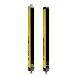
| Height of the protection field | 1,130 mm |
| Range, protection field, minimum | 0.3 m |
| Range, protection field, maximum | 10 m |
| Wave length of the laserdiode | 880 nm |
Mechanical data – Connection technique
| Termination | Connector |
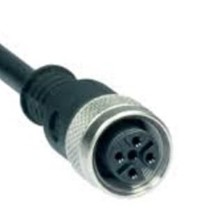
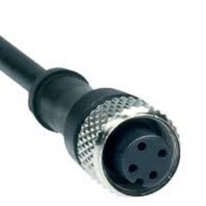
| Terminal connector, Recipient | Connector plug M12, 5-pole |
| Terminal, Connector, Transmitter | Connector plug M12, 4-pole |
| Length of the connectable cable, maximum | 100 m |
Mechanical data – Dimensions
| Length of sensor | 33 mm |
| Width of sensor | 27.8 mm |
| Height of sensor | 1,171 mm |
Ambient conditions
| Degree of protection | IP67 |
| Ambient temperature | -10 … +50 °C |
| Storage and transport temperature | -25 … +70 °C |
| Resistance to vibrations | 10 … 55 Hz |
| Restistance to shock | 10 g, 16 ms, to EN 60028-2-29 |
| Protection class | III |
Electrical data
| Operating voltage | 24 VDC -20 % / +20 % ((PELV) supply unit Imax 1.0 A, according to EN 60204 (power failure ≤ 20 ms)) | |
| Rated operating voltage | 24 VDC | |
| Rated operating current, Emitter | 200 mA | |
| 700 mA |
Electrical data – Control inputs
| Designation, Control inputs | Release / restart interlock |
| Actuation time for manual start | 100 … 1500 ms |
Electrical data – Safety digital outputs
| Designation, Safety outputs | OSSD 1 and OSSD 2 |
| Output current, (fail-safe output), maximum | 0.25 A |
| Design of control elements | OSSD, short-circuit proof, p-type |
| Leakage current Ir, maximum | 1 mA |
| Test pulse interval, typical | 750 ms |
| Test pulse duration, maximum | 0.15 ms |
| Classification ZVEI CB24I, Source | C2 |
| Classification ZVEI CB24I, Sink | C1 C2 |
| Load capacity, maximum | 0.05 µF |
| Load inductance, maximum | 2 H |
| Note | The load inductance generates an induced voltage during the switch-off, which compromises the downstream components (sparkquenching element). |
| Switching voltage | 15 … 26.4 V (HIGH) 0 … 2 V (LOW) |
| Note | According to EN 61131-2 |
| Note | In case of failure, the leakage current flows to the OSSD cable. The downstream control element must recognise this state as LOW. A safety PLC must detect this state. |
LED status display – LED 01
| LED status | OSSD ON, OSSD OFF, Restart interlock, Error, Parameter setting, Alignment kit, Indication of signal quality |
| LED position | Receiver |
LED status display – LED 02
| LED status | transmitting and status |
| LED position | Emitter |
Other data
| Note (applications) | protective mode/automatic, restart interlock, setting mode |
Pin assignment
| Connection | Receiver |
| PIN 1 | 24 VDC power supply |
| PIN 2 | OSSD 1 Safety output 1 |
| PIN 3 | 0 VDC Power supply |
| PIN 4 | OSSD 2 Safety output 2 |
| PIN 5 | Release/restart interlock Acknowledgement restart interlock |
| Connection | Emitter |
| PIN 1 | 24 VDC power supply |
| PIN 2 | Do not connect a signal (do not wire) |
| PIN 3 | 0 VDC power supply |
| PIN 4 | Do not connect a signal (do not wire) |